1. Click to “Start”
after “Mechanical Design” and then “Part Desing”. After these processes a new
tab will be opened (Image-2). This tab allows you to change your part name.

Image- 1
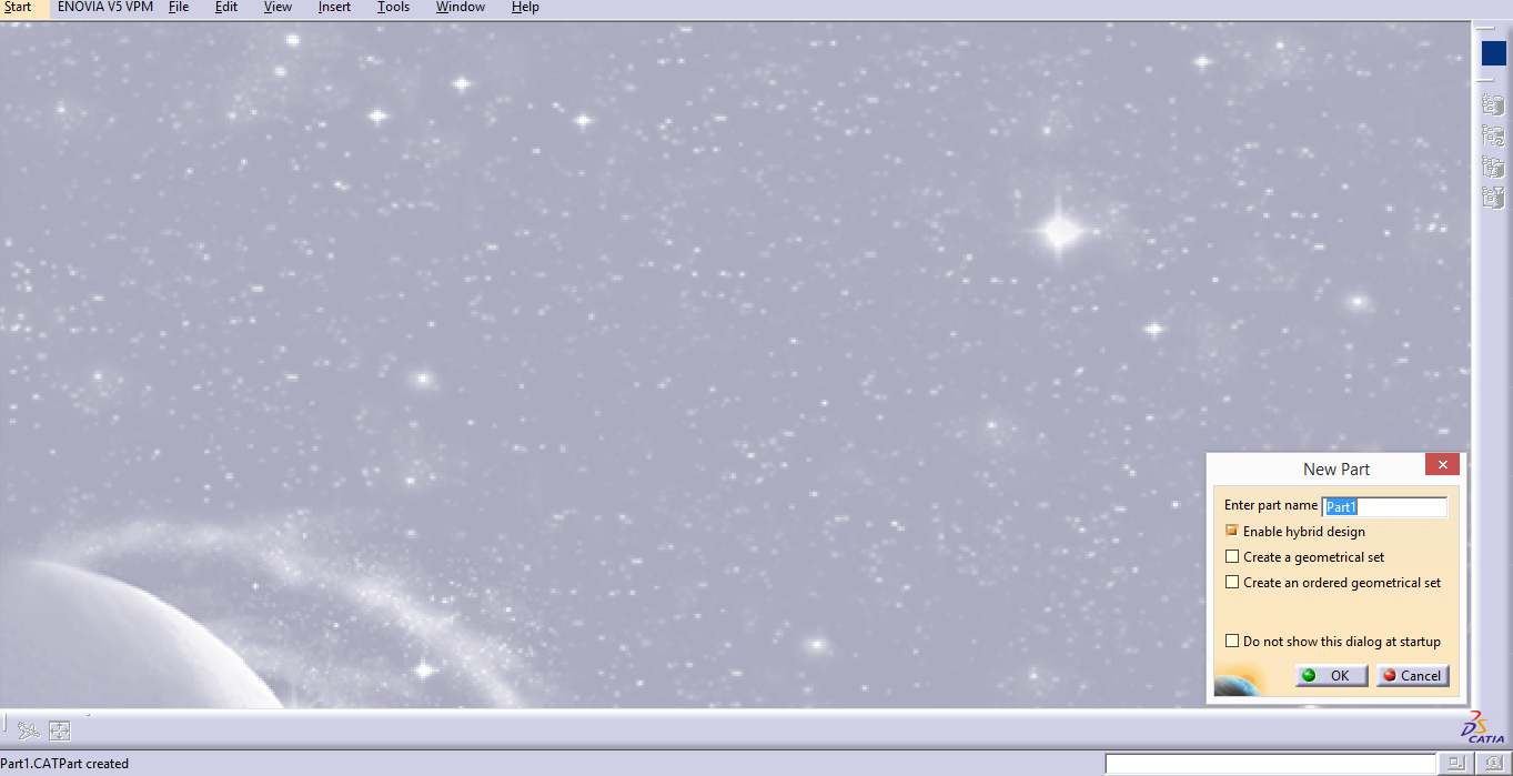
Image- 2
2.After clicking “OK”
on the “New Part” tab.3D modelling work bench will be opened (Image-3).
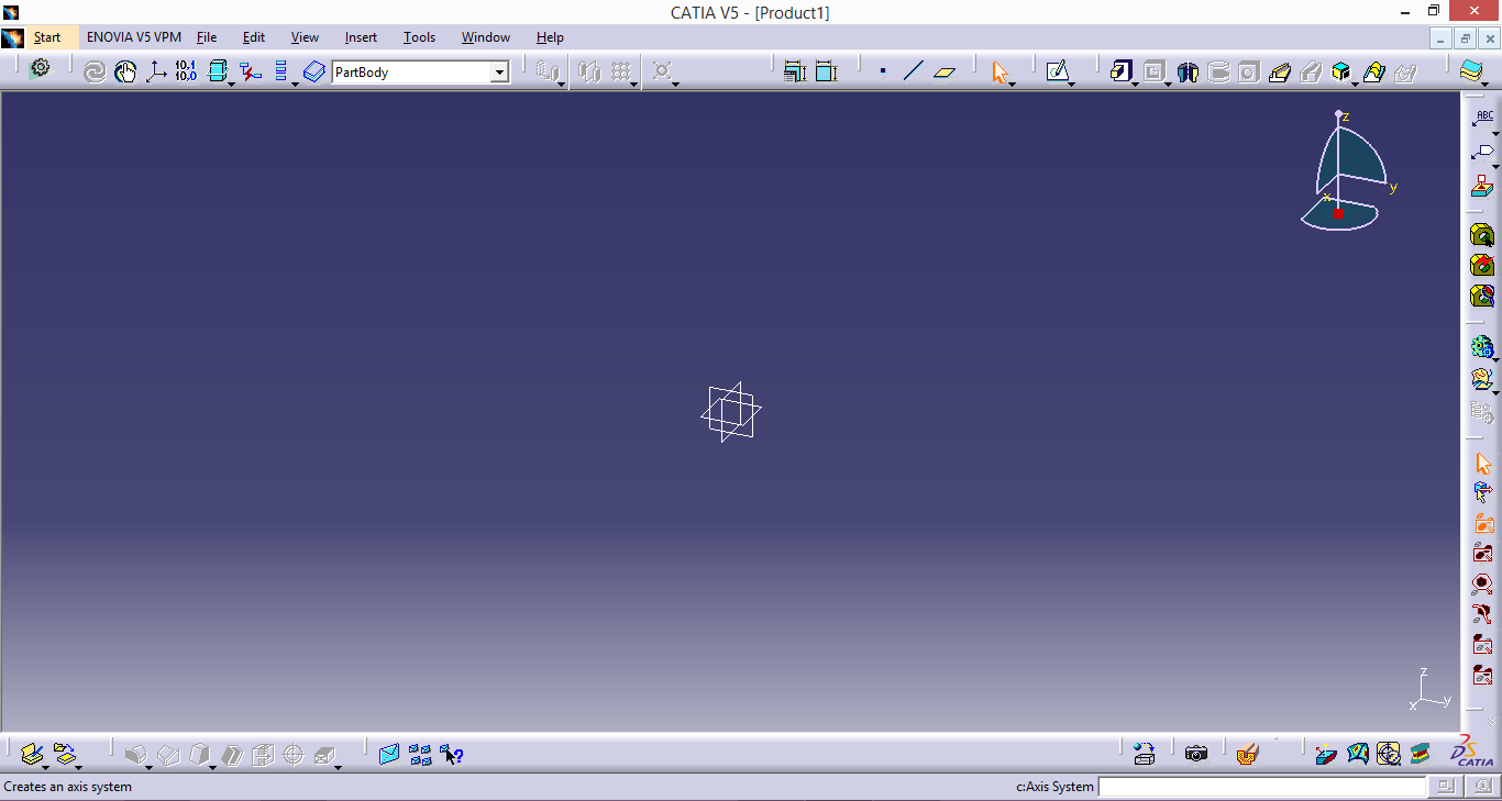
Image- 3
3. Select your
work plane (XY-YZ-ZX), the selected plane become orange after selecting work
plane and click to “Sketch”.

Image- 4
4. On sketcher
modulus select “Profile” toolbar and create your first CATIA drawing by using
Profile


.

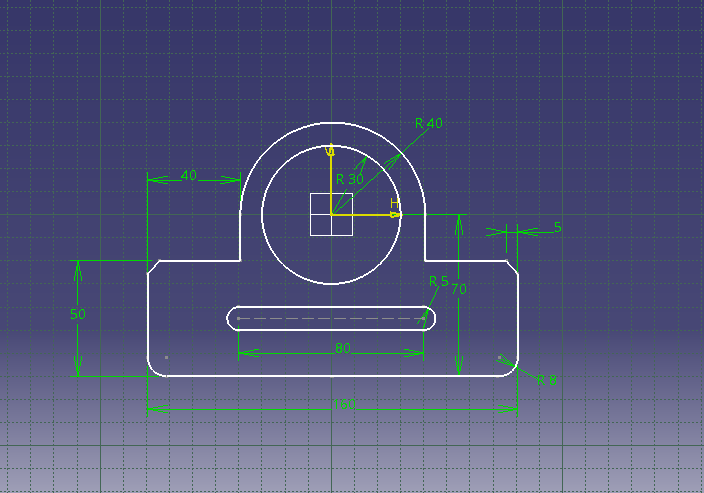
Image- 5

5. From Constraint
toolbar, select Constraint 
NOTE: If you want to save you drawing go to “File” and select “Save
As”.
No comments:
Post a Comment