Labels

Showing posts with label EXERCISES. Show all posts

Saturday, 1 August 2020

EXERCISE- 10: HOW TO DRAW A PERFECT STAR?

       Go to respectively; Start> Shape> Generative Shape Design.


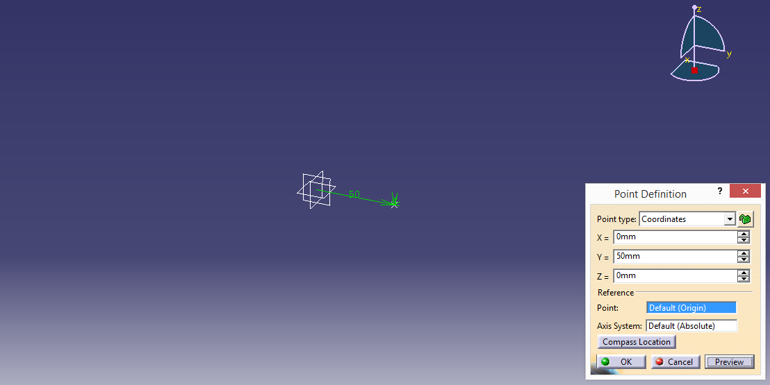
Click “Point” and set coordinates as X= 0, Y= 50, Z= 0. Press “OK”.


 Click “Point” one more time and set coordinates X=0, Y=-25, Z=0. Press “OK”.


 Select “Line Definition” for selected point and select “Create Point” on coordinates (0, 0, 0). Select line type as “Point- Direction” and pick direction as Z component. Set start distance as 12 mm.


  Select (0, 50, 0) coordinated point and go to “Circular Pattern Definition”, set parameters
“Complete Crown”; instances will be “5” and “Z Axis” will be the reference element.


   Select (0, -25, 0) coordinated point and go to “Circular Pattern Definiton”, set parameters as “Instances and angular spacing”, instances: 5, angular spacing: 72 deg and reference element will be “Z Axis”, press “OK”.


Go to “Line Definition” and select parameters respectively as shown below.


Go to “Fill Surface Definition” and select three created lines, press “OK”.


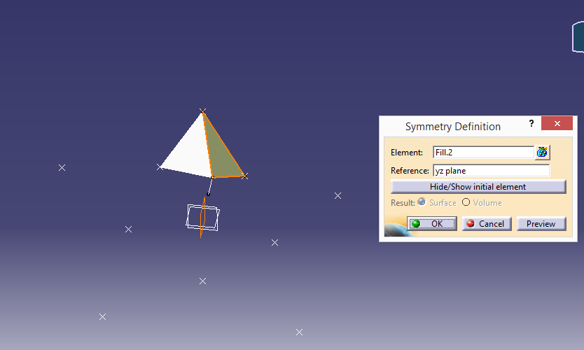
Now, select “Symmetry Definition” as follows and press “OK”.


Select “Join” and pick two pieces to make them one part.


Go to “Circular Pattern Definition”, select the part that recently joined eachother and set reference element on Z Axis.


On join definition part select all the first created part and the rest which has created by using circular pattern definition to join eachother.


Select “Symmetry Definition” to create the pther half of the star. After that click to “Join” to stick two half stars.


The “Perfect Star” is completed. Well done! 


Wednesday, 1 July 2020

EXERCISE- 9


Click Start> Mechanicai Design> Sketcher.

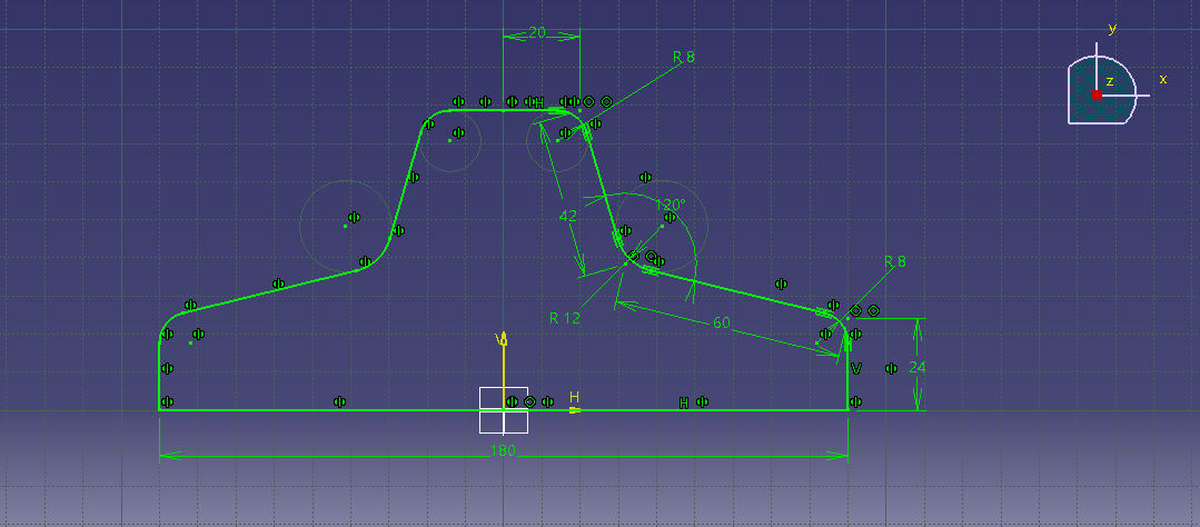
Create sketch on XY plane as shown below with given dimensions:


Exit workbench.

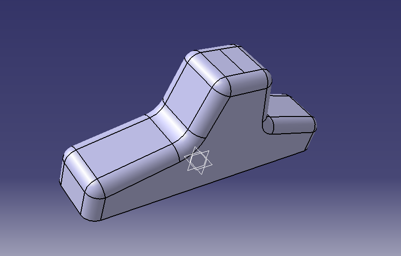
Click “Pad” icon and extrude the selected sketch up to 20mm. by using “Mirrored extent”:


Create fillets with defined dimensions as shown below (r= 8 mm):


Use “Shell” command to empty inside of the part with defined thickness:


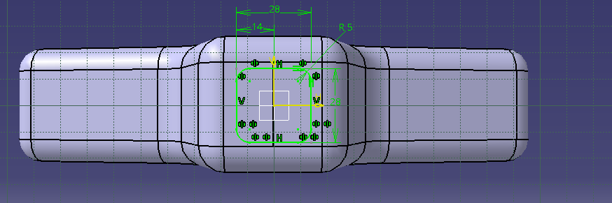
Now select ZX plane and create a sketch on top of the part with specified dimensions:


Exit workbench.

Use “Pocket” to remove sketched part and press “OK”:


Tuesday, 30 June 2020

EXERCISE- 8: HOW TO DRAW A SPRING?

Go to “Start”- “Mechanical Design”- “Part Design”:


Select XY plane and click “Sketch”.

Select “Point” from “Profile” toolbar.

Set the point distance as 15 mm from the origin and press “OK” (You can set distances by using “Constraints”):


Exit workbench.

Now, there are two options avaliable to draw a helical shape. First, you can enter “c:helix” to the command line. Second, you can go to “Start- Shape- Generative Shape Design” but you should turn back to “Part Design” again. On this article, i am going to show the first one because I have showed the second option on previous post.


Write “c:helix” to the command line and press ”ENTER”:


Apply helix dimensions as follows:


Select ZX plane and click “Sketch”.

Draw a 1,5 mm diameter circle coincide center of the circle with defined point of the helix:


Exit workbench.

Go to “Rib”, select helix as “Center curve” and profile as “Sketch.2” to fianlize the part.


EXERCISE- 7: HOW TO DRAW A NUT?

Go to “Start”- “Mechanical Design”- “Part Design”.

Select XY plane and click “Sketch”.

Select “Hexagon” icon from “Profile” toolbar.

Draw a hexagon and circle as defined dimensions:


Exit workbench.

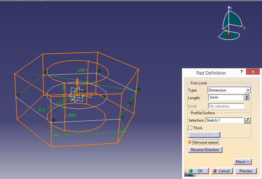
Go to “Pad Definition” and set length as 5mm by clicking “Mirrored extend”, press “OK”:


Now select YZ plane and click “Sketch”.

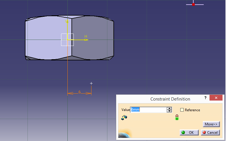
Draw a triangle with defined dimension as below:


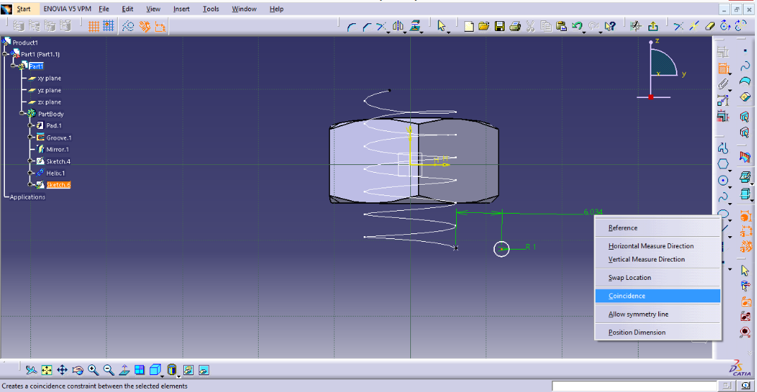
Select top right point of the shape and select left point of the triangle and use “Coincidence” command by clicking right button of mouse.


Exit workbench.

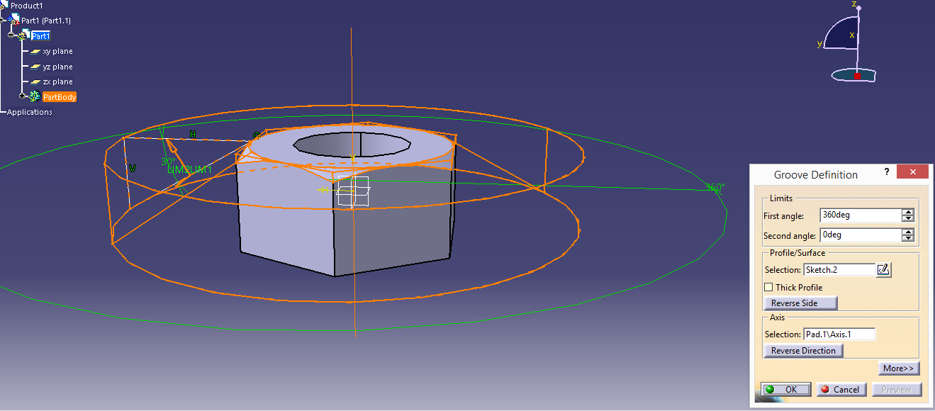
Select “Groove” command and set dimensions as follows:


Select “Groove” from product tree and click “Mirror” (You will see a “Warning”, press “YES” and continue.). Select XY plane to mirror it.


Go to YZ plane click “Sketch” and select “Point” icon. Apply the dimensions as below:


Exit workbench.


Go to “Start”- “Shape”- “Generative Shape Design”.  Select “Helix” icon and apply the dimensions as follows:


Go back to “Part design” and select YZ plane. Click “Circle” icon and coincide the center of the circle and bottom point of the helix. (Circle radius is 1mm).


Go to “Slot” and click “Helix” for center curve  at “Slot Definition” to finalize the part.