Tuesday 30 June 2020

EXERCISE- 8: HOW TO DRAW A SPRING?

Go to “Start”- “Mechanical Design”- “Part Design”:


Select XY plane and click “Sketch”.

Select “Point” from “Profile” toolbar.

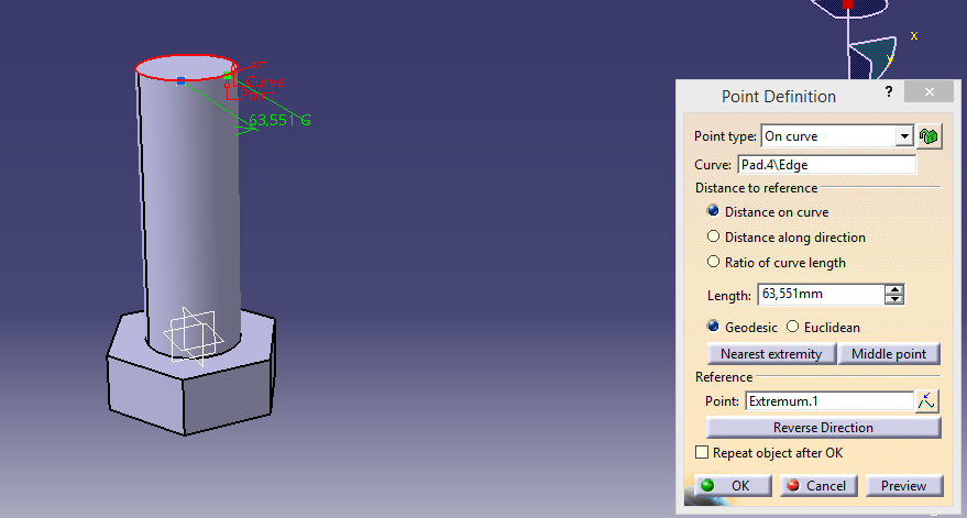
Set the point distance as 15 mm from the origin and press “OK” (You can set distances by using “Constraints”):


Exit workbench.

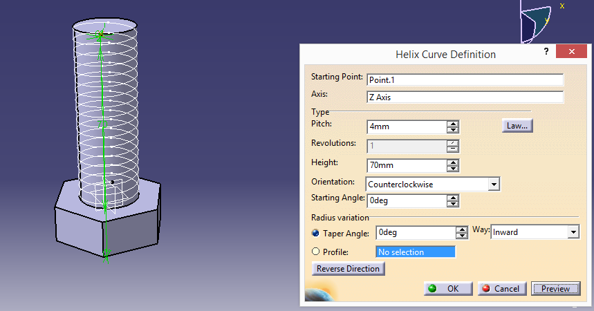
Now, there are two options avaliable to draw a helical shape. First, you can enter “c:helix” to the command line. Second, you can go to “Start- Shape- Generative Shape Design” but you should turn back to “Part Design” again. On this article, i am going to show the first one because I have showed the second option on previous post.


Write “c:helix” to the command line and press ”ENTER”:


Apply helix dimensions as follows:


Select ZX plane and click “Sketch”.

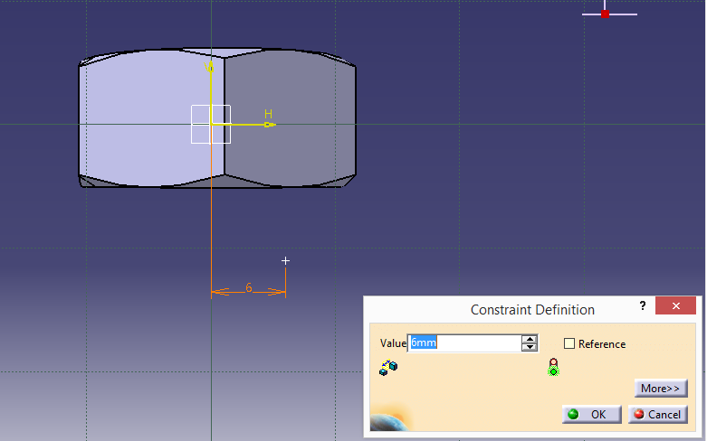
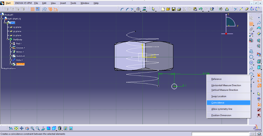
Draw a 1,5 mm diameter circle coincide center of the circle with defined point of the helix:


Exit workbench.

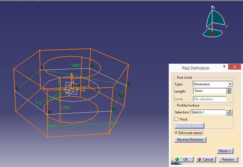
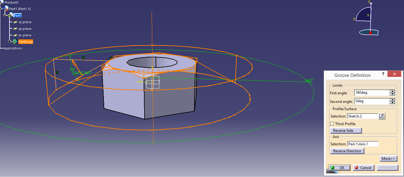
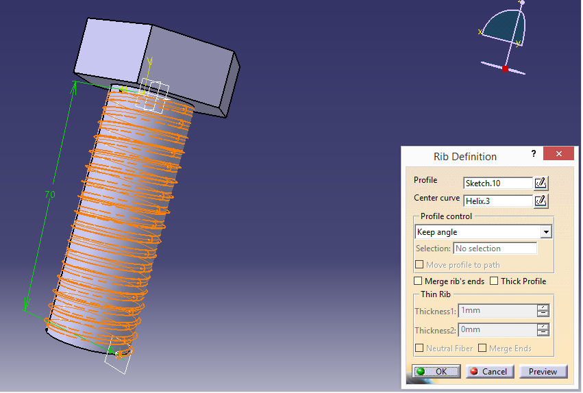
Go to “Rib”, select helix as “Center curve” and profile as “Sketch.2” to fianlize the part.


EXERCISE- 7: HOW TO DRAW A NUT?

Go to “Start”- “Mechanical Design”- “Part Design”.

Select XY plane and click “Sketch”.

Select “Hexagon” icon from “Profile” toolbar.

Draw a hexagon and circle as defined dimensions:


Exit workbench.

Go to “Pad Definition” and set length as 5mm by clicking “Mirrored extend”, press “OK”:


Now select YZ plane and click “Sketch”.

Draw a triangle with defined dimension as below:


Select top right point of the shape and select left point of the triangle and use “Coincidence” command by clicking right button of mouse.


Exit workbench.

Select “Groove” command and set dimensions as follows:


Select “Groove” from product tree and click “Mirror” (You will see a “Warning”, press “YES” and continue.). Select XY plane to mirror it.


Go to YZ plane click “Sketch” and select “Point” icon. Apply the dimensions as below:


Exit workbench.


Go to “Start”- “Shape”- “Generative Shape Design”.  Select “Helix” icon and apply the dimensions as follows:


Go back to “Part design” and select YZ plane. Click “Circle” icon and coincide the center of the circle and bottom point of the helix. (Circle radius is 1mm).


Go to “Slot” and click “Helix” for center curve  at “Slot Definition” to finalize the part.


Monday 29 June 2020

EXERCISE- 6: HOW TO DRAW A BOLT?

Click “Start”- “Mechanical Design”- “Part Design”.
Select XY plane and create a hexagon with defined dimension (40 mm).


Exit workbench and click to “Pad” and enter the length as 15 mm.
Select bottom side of the shape and click “Sketch” to draw a circle as 12 mm diameter.
Exit workbench and click “Pad” , enter the length as 70 mm.


After padding process, the helix start point must be defined as follows:


Click star and select “Generative Shape Design” from “Shape” section.
Click “Helix” and select “Helix Curve Definition”. Apply the defined dimensions as below:


Go to “Part Design” from “Start”. Select “Plane” and select “Plane type” as “Normal to Curve”, “Curve” as “Helix.1” and “Point” as “Point.1”.


Click to “Plane” and draw a circle as below:


Exit workbench.
Go to “Rib Definiton” and select the curve, press “ OK”.

Friday 26 June 2020

EXERCISE- 5: HOW TO USE SHELL COMMAND?


Select “Start”- “Mechanical Design”- “Part Design”.
Click “Sketch” and use YZ plane.
Draw the shape as below and mirror it:


Exit workbench.
Go to “Sketch- Based Features” toolbar and select “Pad” and enter the value to the “Length” box, select ”Mirrored extent”:


Press “OK” to complete.
Click to “Dress-Up Features” and select “Draft Angle”, apply selection as follows:


The part that you want to change with angle must be red and stable part must be blue.
To give radius to the edges, click to “Edge Fillet” icon.


To give a shape as below, click to “Tritangent Fillet” and create radius to a greater extent.


Click to “Shell” icon and enter the “Default outside thickness” value as 3mm after that select the surfaces which will be removed:


Tuesday 23 June 2020

EXERCISE-4: HOW TO USE SOLID COMBINE COMMAND?


Click “Start”, select “Mechanical Desing” and then “Part Design”.
Mirror the shape by using Z axis:


Exit workbench.
Select ZX plane and let’s start to draw our second profile:
On that plane select “Elongated Hole” and draw a shape as follow:


Exit workbench.
Click ”Solid Combine” from “Sketch- Based Features” toolbar.


Select our first profile after the second one.
Finally, you will create a shape as below: