1. Essential Toolbars
1.1. Standard

 | New | To open a new file and after select file type |
 | Open | To open saved files |
 | Save | This tool helps to you to save your files |
 | Quick Print | This tool prints the selected file |
 | Cut | When the commend deleted by taking a copy |
 | Copy | It helps to get a copy of selected objects |
 | Paste | This tool helps to paste the copied object |
 | Undo | It helps you to step backwards |
 | Redo | When undo your command it helps you to refresh and undo your undo |
 | What's This? | This tool gives an information for selected command or object |
1.2. View

 | Fly Mode | To show perspective view |
 | Fit All In | To center the selected object |
 | Pan | To move screen view in any direction. Like melting butter on the pan |
 | Rotate | To rotate screen view. You can use any mouse button(MB1,MB2 or Wheel) for rotate by holding down the one button |
 | Zoom In | To zoom in the view by clicking MB2 |
 | Zoom Out | To zoom out the view by clicking MB2 |
 | Normal View | To select a planner suface and your view will be rotated automatically to the perpendicular form to the selected planner surface |
 | Create Multi View | To divide four the sketching area |
 | Isometric View | This tool allows you to rotate your object to isometric view |
 | Shading with Edges | With this tool you can decide how to represent your part |
 | Hide Show | In your working space if you don't want to see any part of your complex object, you can choose this by clicking MB1. When your object is ready you can pull back easily |
 | Swap Visible Space | It allows you to move your selected element to no show space.If you want it back, you can click that button again |
1.3. Select
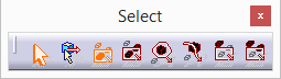
 | Select | The standard way of selecting object |
 | Selection Trap Above Geometry | This one allows you trap on a specific element |
 | Rectangle Select Above Geometry | This allows you to select objects inside of the box |
 | Intersecting Rectangle Selection Trap | To make a box and select items which they are cut |
 | Polygon Selection Trap | To make a polygon and select elements inside of that geometry |
 | Free Hand Selection Trap | By this option you can create a free hand lines |
 | Outside Rectangle Selection Trap | This selects everything outside of the window |
 | Outside Intersecting Rectangle Selection Trap | This selects everything and intersecting outside of the window |
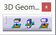
2. 2D Sketcher Toolbars
2.1. Constraint

 | Constraint Defined Dialog Box | It helps to you to measure some geometrical feautres of your element |
 | Constraint | It allows you to make quick measurement |
 | Fix Together | This tool sticks the selected elements and allow to fix together |
 | Animate Contraints | It allows to simulate the mechanism in the sketch |
 | Edit Multi Constraint | This tool allows you to change the measures of the sketch pratically |
NOTE: By the help of "Constraint Defined Dialog Box" you can measure or view things such as below;
- Distance
- Length
- Angle
- Radius/ Diameter
- Semimajor Axis
- Semiminor Axis
- Symmetry
- Middle Point
- Equidistant Point
- Fix
- Coincidence
- Concentricity
- Tangency
- Parallelism
- Perpendicularity
- Horizontality
- Verticality
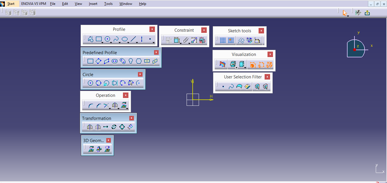
2.2 Profile Toolbar and Profile Sub-Toolbars
2.2.1. Profile
 | Profile | This tool allows you to create adjecent lines or arcs, the process will not end unless you do not double click to mouse |
2.2.2. Prodefined Profile
 | Rectangle | This tools allows you to create a rectangle by selecting two points |
 | Oriented Rectangle | It allows you to create a rectangle by selecting three points |
 | Parallelogram | It allows you to create parallel lines with the same technique of the "Oriented Rectangle" |
 | Elongated Hole | This tool allows you to draw a linear chamfer. After clicking to command button repectively you can input the center of the first circle, center of the second circle and the diameter of the circle |
 | Cylindrical Elongated Hole | This tools allow you to create curvilinear chamfer by using the same techniques "Elongated Hole" |
 | Keyhole Profile | It allows you to create keyhole easily |
 | Hexagon | This tools is use for draw a hexagon. After clicking command button the first point is selected and then the second must be the middle point of one margin |
 | Centered Rectangle | It is use for to draw a rectangle which the center is known |
 | Centered Parallelogram | It is use for to draw a parallel which the center is known, for this process we need two non-paralel lines to use this command |
2.2.3. Circle
 | Circle | To draw a circle, the center point is the first click of the mouse |
 | Three Point Circle | It creates a circle by defining three points which is circle passes on |
 | Circle Using Coordinates | It allows you to draw a circle by the help of coordinate system |
 | Tri Tangent Circle | It allows you to draw a circle whose perimeter is tangent to three selected lines |
 | Three Point Arc | It creates an arc from defined three points |
 | Three Point Arc Starting With Limits | It allows you to draw an arc with three limits by using start point, midpoint and end point |
 | Arc | This command allow you to create an arc with defined center point |
2.2.4. Spline
 | Spline | It allows you to create curved profile defined by points |
 | Connect | This tool allows you to connect profile or two points to spline |
2.2.5. Conic
 | Ellipse | To draw an ellipse these steps must be followed; first center point and then large diameter and small diameter after clicking the command button |
 | Parabola by Focus | It allows you to draw a parabola |
 | Hyperbola by Focus | This tool allows you to create a hyperbola |
 | Conic | It allows you to create a conic |
2.2.6. Line
 | Line | It allows you to draw a standard line with defined start and end point |
 | Infinite Line | The infinite line allows you to create an infinite line |
 | Bi Tangent Line | It draws a lines from tangents of two objects |
 | Bi Secting Line | It draws an infinite line which bisects the angle drawed by two different lines |
 | Line Normal to Curve | It allows you draw a perpendicular line from defined shape |
| Axis | It creates an axis |
2.2.7. Point
 | Point | It allows you to put points |
 | Point by Using Coordinates | This tool allows you to put points by the help of coordinate system |
 | Equidistant Point | It helps you to put point on a defined curve or line |
 | Intersection Point | It creates a point on intersection of two different lines |
 | Projection Point | By projection point, you can create projection point on a defined curve |
2.3. Operation

 | Corner | It allows you to give radius on intersecting point of two sharp edges |
 | Chamfer | It allows you to create a chamfer between intersecting point of two edges |
2.3.1. Relimitations

 | Trim | This tools helps you to cut required lines |
 | Break | It allows you to break lines |
 | Quick Trim | It helps to delete unwanted elements on project |
 | Close Arc | It helps you to complete the arc or ellipse |
 | Complement | This tool deletes the and arc or ellipse and creates it is complement |
2.3.2. Transformation
 | Mirror | Mirrors image on defined axis |
 | Symmetry | It replaces sketch by taking it is mirror image |
| Translate | It duplicates objects on requested amout, on requested direction and defined length | |
 | Rotate | It duplicates objects to requested amount and angle around selected on reference center |
 | Scale | It scales a sketch on defined point relatively |
 | Offset | By a defined distance it shifts an object on required amount |
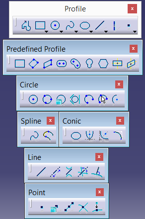
2.3.3. 3D Geometry
 | Project 3D Elements | This tool allows you to project edged of the drawn object on the sketch plane |
 | Intersect 3D Elements | It helps you to measure the intersection between sketch plane and 3D element |
 | Project 3D Silhoutte Edges | It shows reflection of the selected circular surface to sketch plane |
2.4. Sketch Tools

 | Grid | It creates grid to draw a sketch easily |
 | Snap to Point | It allows to snap command active or inactive |
 | Construction/Standard Element | This tool allows to converse lines to construction element |
 | Geometrical Constraints | It automatically places geometric limits such as; vertical, horizontal, tangent, parallel or conicident during sketching |
 | Dimensional Constraints | This command must be active during sketching to use line length, angle value measurements |
2.5. User Selection Filter

 | Point Filter | It only allows to select points on the sketch |
 | Curve Filter | It only allows to select edge lines of 3D Model which is belongs to sketch lines |
 | Surface Filter | By clicking command button it only allows to select surfaces |
 | Volume Filter | This tool allows to select all solid model |
 | Feature Element Filter | This command allows to filter rounded corner, hole and chamfer on 3D Model |
 | Geometrical Element Filter | It only allows to select geometrical elements (e.g. Axis of Cylindrical Surface) |
No comments:
Post a Comment